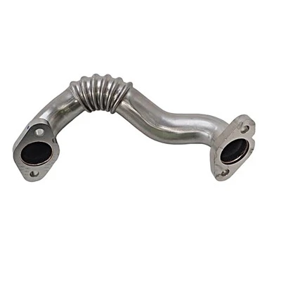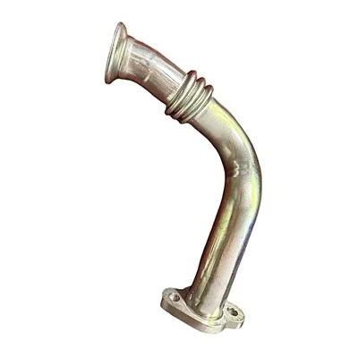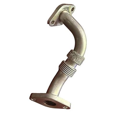

The engine intake hose is a key connecting component in the internal combustion engine intake system. It is usually made of rubber or silicone material, and its two ends are connected to the air filter outlet and the engine intake manifold respectively.
The installation process begins with the removal of the old hose. Before disassembly, make sure the engine is completely cool to prevent burns and component deformation. Use special clamp pliers to loosen the fixed clamps at both ends, rotate gently along the axial direction and pull out the hose to avoid stress damage to adjacent sensor lines or brackets. At this time, it is necessary to simultaneously check the intake manifold interface and air filter interface exposed after disassembly to observe whether there are oil deposits, cracks or deformations. These details directly affect the subsequent sealing effect.
Installation of new hose is subject to a fit verification process. First, compare the matching between the inner and outer diameters of the hoses and the size of the interface. It is found that silicone hoses have a more stable thermal expansion coefficient in Hebei's environment with large temperature differences. Before installation, a small amount of silicone-based lubricant can be evenly applied on the outside of the interface. This can reduce frictional resistance without damaging the rubber molecular structure. When inserting the hose, the axes of the interfaces at both ends should be kept aligned, and a spiral push method should be used to gradually insert the hose to the root of the interface to prevent local distortion from causing turbulence in the internal air flow.
The clamp fixing link reflects engineering precision. The stainless steel worm clamp needs to be placed parallel to the end face of the interface. During the tightening process, use a torque wrench to apply force in three crosswise increments until the standard torque value is reached. Over-tightening will cause local compression and deformation of the hose, which will in turn destroy the even pressure distribution on the sealing surface. After the fixation is completed, you need to manually check circumferentially whether there is any detectable displacement gap between the hose and the interface.
Air tightness verification forms a closed loop in the installation process. Start the engine to idle speed, use professional leak detection spray to evenly spray the joints at both ends, and observe the foam formation. For more accurate detection, the intake pressure tester can be connected to the diagnostic interface to monitor the intake pressure curve fluctuations under idle and rapid acceleration conditions. In the windy and sandy environment in Hebei, it is recommended to install an additional dust-proof sealing ring on the air filter end as a redundant protection.
Long-term maintenance strategies focus on preventive inspection of nodes. The surface of the hose should be visually inspected every quarter for fine lines and hardening, focusing on sections of the pipe body close to the high-temperature areas of the engine. After experiencing extreme temperature change cycles, it is necessary to recheck whether the clamp torque value is attenuated due to material creep. If oil mist is found adhering to the inner wall of the hose, it may indicate that the upstream crankcase ventilation system needs simultaneous maintenance.
The optimization direction of the installation process is reflected in the level of system collaboration. The efficiency of the air intake hose not only depends on its installation accuracy, but also is related to the resonant frequency of the entire air intake system. When modifying or replacing hoses made of different materials, it is necessary to calculate the impact of pipe volume changes on the intake resonance point, and if necessary, adjust the air flow meter calibration parameters to achieve system rebalancing. If users in the Hebei area often drive in dusty conditions, they may consider adding a pre-filter device upstream of the hose, but they need to re-evaluate the flow resistance characteristics of the entire air intake system.
The stability of hose installation needs to be verified through multi-dimensional parameters. In addition to basic air tightness indicators, attention should also be paid to the intake air temperature change curve of the engine under different load conditions. Abnormal temperature fluctuations may indicate that there is a local heat conduction bottleneck in the hose. For turbocharged models, the fatigue resistance of the hose in a pressure pulsating environment needs to be particularly checked. The tensile strength of the material should reach a safety factor of more than 3 times the standard atmospheric pressure value.
Advances in materials science provide new ways to improve hose performance. The new composite laminate material can effectively block the interference of engine compartment heat on the intake air temperature while maintaining flexibility. Some high-end models adopt a spiral flow guide structure on the inner wall, which can increase the intensity of the intake vortex without increasing flow resistance. Although these technological innovations do not change the basic installation process, they require installers to master the ability to identify material properties to avoid improper installation methods from damaging special structural layers.
The final installation effect evaluation should be completed in the vehicle operating system. Continuously monitor the short-term fuel correction coefficient and long-term fuel correction coefficient during three complete driving cycles. Only data that is stably maintained within the standard range can prove that the air intake system has reached the ideal working condition.